SV Portal Forums banner

SECONDARY THROTTLE VALVE ADJUSTMENT

90K views 104 replies 57 participants last post by  Missing Link  
#1 ·
Well, it's a long time coming, with me having to move to a new residence and such, but I promised AndyW I'd get the job done.

Secondary throttle valves....There are many thoughts on just what the heck they do. Some say it's for noise abatement, others think they just get in the way, and affect the true performance of the bike, and some would just rather remove them.

I should point you in the direction of my tech article about Carburetors.
More directed to the "Constant Velocity" type.

Since the introduction of fuel injection, we no longer require a pressure drop through a ventury to pull fuel from a fuel bowl, and introduce it into the engine. We have a fuel pump that sends pressurized fuel to fuel injectors, and thanks to IC chips, and sensors, we can spray the fuel into the engine. No need for fancy needle jets, main jets, primary jets, and airbleed jets. Nevermind making sure the fuel level in the carb bowls is the correct height.

There is one thing that's important with the CV carburetor, and that's how it keeps the air velocity constant through the intake ports regardless of throttle position. If you ever had flat slide carbs, and immediately opened the throttle, you would notice that the engine would take a big gulp of air, and hesitate, or even stall. Accelerator pumps were introduced to keep this in check. So, in regards to keeping air velocities constant especially at lower engine rpms, one concept for a fuel injected engine is to add separately controlled throttle plates that can move independently from the main throttle plates. This way, if the throttle plates are opened quickly, air velocity will drop, but with the Secondary Throttle plates lagging just behind, can keep the air velocity up, and help with atomization of the fuel injected into the engine. of course if you are racing the bike, and it never sees rpms below 6 to 7,000 rpms, there is no sense on having the secondary throttle plates there, and can be removed for some added increase of air. Most of us don't race, and use the engine through a wide range of rpms, and with the STV's installed really doesn't detract from performance, but keeps it more tractable.

Now, enough said about how they work, lets see how we adjust them.

Maui, aka (Dave), was kind enough to donate his bike, (and get some free work done) by yours truely.

We first started to check his Throttle position sensor... (see Chewy's killer Tech tip), and found that we needed to make a small adjustment.

After that was all and done, we had at the STV's.
There are basically 3 parts to this arrangement.
1. The STV's.
2. The servo motor that drives them.
3. The STV position sensor that tells the ECU where they are in position.

First thing to do is raise the tank, and remove the airbox assembly. Those Pair valve hoses are a BITCH! (Hint Dave...Loose the pair..)
There are several connectors that need to be uncoupled to facilitate the removal. Just remember where they go, once you tend to the task at hand.

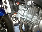
First thing to identify, is the STV's it's kind of a no brainer, but we want to cover everything...This is pic #1

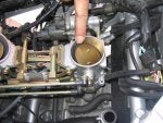
Next is the servo mechanism, pic #2

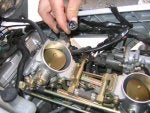
And finally the STV position sensor pic #3

We now want to find the connector at the STV positon sensor, the wire loom is actually folded and tied together. pic #4.
 

Attachments

#27 ·
I finally got around to checking mine and... I found a different problem. The secondary thottles did not have matching angles. They were not closing or opening at the same time. After matching the blades, I set the sensor to better track the small angle requirements and.... WOW. Whole new bike.

O
 
#28 ·
A little scarey to read and comprehend but actually doing it was fairly simple and I felt that there was a better response around 4500 RPM to 7000 RPM. My readings were quite a bit off and had to find the 'happy medium'. Not quite as Suzuki specs it out but fairly close. Thanks to TLRman for that informative lesson.

This site is DA BOMB for information. Can you imagine how much 'we' would have spent by now to do all the things that normal 'nonmechanics' wouldn't have had a clue how to do???:crazy:
 
#29 ·
What range to use?

I thought I'd try this today and treid TLRman's method and Suzuki's; got his:

Resistance: OPEN = 4 MAX - 3.5 Min (3.9 start)
CLOSED = 1 Max - 0.5 Min (0.58 start

Voltage: OPEN = 3.5 Max - 2.5 MIN

Decided to set at Max position, was this right???
 
#30 ·
Valves said:
I thought I'd try this today and treid TLRman's method and Suzuki's; got his:

Resistance: OPEN = 4 MAX - 3.5 Min (3.9 start)
CLOSED = 1 Max - 0.5 Min (0.58 start

Voltage: OPEN = 3.5 Max - 2.5 MIN

Decided to set at Max position, was this right???

Well, from a man who uses tolerances every day..as long as you are within them, you are good to go.
 
#32 ·
Okay, so here's what I've got. 03 silver SV1000S, M4 2-into-1, K&N, de-snorkeled and tank lifted ~1cm, PAIR yanked and blocked, Simplest Smart TRE ever, mapped +5L+5M+5H +2.5 idle using homemade Yosh box clone, 16-39 (soon to be 16-42) 520 conversion, '06 GSXR1000 shock, TPS adjusted, TBs synced, STVs adjusted to the middle of the range as per this thread. I have it running about as good as it may ever need to. Its awesome. Great crisp throttle response, and good pull through the RPM range. It's set up to be a fun touring-sportbike, and I rarely burn less than a tankful per outing. The only thing I can't figure out is how to get those STV butterflies to do their open-close dance in a different range. Right now they are most pronounced from 5500-6000, which is incidentally my favorite cruising range. If I adjust the SVT position sensor to a different setting would that move the open-close correspondingly? I'm not sure if its a linear relationship between the sensor, the ECM, and the servo, or a simpler binary one. I might just yank em if nothing else. Sorry to rehash such an old thread, but any ideas?

Thanks for reading,
John
 
#34 ·
interesting will have to check mine:nutkick:
 
#35 ·
OK I just got done checking my STV and adjusting them,and the best numbers I can come up with are

closed .60

open 4.28

voltage check 4

:buggerd::buggerd::buggerd::buggerd::buggerd:
 
#36 ·
Well I just adjusted mine.

I've having problems with random FI error C28 (STVA) So I thought I'd have a play with this too.

Initial my readings were 0.95 closed and 4.67 open.
After adjusting it as far as it would go, i ended up with 0.72 closed and 4.54 open.

The only way I can get more is to file out the holes in the sensor more. Might be a job for a Winters weekend. Weather is too good at the moment :)
 
#37 ·
adjusted my STV sensor

Factory spec is:
measured between the yellow and black wires (on the sensor)
valve closed = .58 K ohms
valve open = 4.38 K ohms

Mine was,
valve closed = .97 K ohms
valve open = 4.55 K ohms

I removed the metal inserts, widened the holes in the sensor, and then installed new screws with larger washers spread the load over more of the sensors plastic mounting tabs.

After adjusment
valve closed = .51 K ohms
valve open = 4.12 K ohms

A proper test ride will have to wait till next weekend.

~Jeffers
 
#39 · (Edited)
After todays test ride

First a recap of what I adjusted,

measured between the yellow and black wires (on the sensor) Factory spec is:
valve closed = .58 K ohms
valve open = 4.38 K ohms

This is what I measured before adjusting.
valve closed = .97 K ohms
valve open = 4.55 K ohms
(this would signal the ECU a larger than actual valve opening) Riding the bike in the past in certain conditions is has felt like the STV were a little slow to open.

I removed the metal inserts, widened the holes in the sensor, and then installed new screws with larger washers to spread the load over more of the sensors plastic mounting tabs.

After adjusment it was.
valve closed = .51 K ohms
valve open = 4.12 K ohms (this signal should advance the servo motor's opening of the valves)


After today's test ride (140 miles) I think this adjustment has made an improvement. When I first left on the bike today , the FI light stayed on, and I cursed myself for not taking a test ride last weekend after the adjustment. But after stopping for fuel and shutting the bike off. The light reset, and hasn't come back on since. The bike seems to pull from 3-4000 rpm a bit better. Best I can discribe it is stronger pulses, like better cylinder filling. The bike feels more like my old SuperHawk that seemed to pull stronger from low rpm than the SV. My bike is stock from the snorkle to the stock pipes, even the California emissions plumbing is intacked. This adjustment probably gives a few more degrees of opening on the STV valves. But might make the bike more prone to pinging with regular fuel. The SV is high compression compared to the SuperHawk and the STV valves may reduce cylinder filling under high load/low rpm/wide throttle conditions where knock can occur.
Anyway so far, so good. Now why did Suzuki give a spec for the STV sensor that can't be acheived without removing the metal inserts and widening the holes in the sensors mounting tabs?? The bike seems to run better set to spec or actually .51 K ohms from .97 K ohms I found it at.
Spec is .58 K ohms.

Update 04-06-08

Turns out the FI light comes on when the engine's cold and resets if you re-start the engine after it warms up. So I've re-adjusted the sensor to .60 K ohms. 4.23 K ohms open.
 
#40 ·
Not to stir up an old thread, but heres a fun tidbit for yall trying to make adjustments. If you have a TRE it could interfere with proper setting! I noticed something a bit intresting yesterday. If the bike was in gear, clutch pulled it would idle at curb idle speed. As soon as the clutch saftey switch would click off, it would raise a few rpm (50-75ish). If the gear position is in N, then it stays at curb idle. Im not yet sure if it effects the STV's or not, but im not sure where the increase in rpm is from. (possibly altering timing or mixture, clutch in you dont need performance)
 
#43 ·
STV sensor adjustment

I had a go at adjusting mine last weekend, and found that before adjusting anything, they were pretty much the same as others have reported. I had started experiencing the surge at around 3000rpm, but also realized that I should have changed the plugs at 12000km (was at 20000km at the time :blush: ). This mostly cured the problem, although it didn’t seem to be quite as smooth as I remembered. Fuel consumption was also higher than it was previously.

Using only the actuator to move the butterflies through their range, they measured:
Closed: 0.83
Open: 4.40
Range: 3.57
Avg: 2.62

I adjusted them as follows:
Closed: 0.66
Open: 4.23
Range: 3.57
Avg: 2.45

As the standard median value is 2.48kΩ, I was happy with this (I could not get it any closer). By taking up the slack, the range increased to 0.52 – 4.41, but the second valve cannot normally move over this range without finger pressure.

The result was definitely noticeable, being smoother from ~2500rpm upwards, and my fuel consumption has dropped to what it was previously. As I use my bike as transport, smooth throttle response at low revs is important, particularly in the wet.

Many thanks to TLRMan, and others who contributed, for the guidance. Next is the TRE mod.

Cheers,
Tony.
 
#44 ·
STV adjustment re-visited

I had another look at the STV’s recently, just to satisfy my naturally inquisitive nature (read anal-retentive), and found that the butterflies where not quite vertical (relative to each one's throttle body) at the full open position. The Suzuki manual says nothing about this, the setup procedure being performed at the closed position. I also noticed that the two butterflies appeared to be slightly out of sync.

The manual gives the sync procedure with them both horizontal, which by the way, is not at the limit of the actuator’s range of travel. At the limit of travel, the valves are actually past closed, and the range of movement provided by the actuator is greater than 90º (?), although they probably never close past horizontal by themselves (not as I have observed, anyway).

I first synced them at the horizontal position, as described in the manual, and then checked them at fully open, where they were not fully vertical. The adjustment of the valves relative to the motor is controlled by a screw on the connection between the actuator and the front valve, although the manual says nothing about this either (apart from stating that you shouldn’t dissemble it unless it cannot be avoided :p ). I then adjusted this screw at the closed position, opened the valves fully to check, closed and adjusted, opened to check …, until finally they were fully vertical at this limit of the actuator’s travel.

I then re-adjusted the STV sensor as described in my post above, averaging the fully open and fully closed values to obtain the mid-point of the range specified. One thing that did cause some worry was the amount of play in the linkage system between the two valves, but I chose to ignore this once I observed them in operation. When the engine is cold, the valves will move to the fully open position when the ignition is turned on, and both valves were now fully vertical. As the engine warms up, they slowly move towards a closed position, although even when hot, they were never quite closed. If the ignition is turned on when the engine is warm, they move from a partially open position to fully open, and back to the original position (as described in the manual).

I did not notice any difference when riding the bike after this adjustment, but at least I know that when WFO, the STV’s are also wide open (there are definitely drawbacks to being a Virgo :) ).

Hope this provides some useful info to others who may have the desire to fiddle.
 
#46 ·
Finally got around to checking all the adjustments and I just wanted to let everyone know a easy way to move the STV's without removing the airbox.

I simply used a long 1/4" extension with a 8mm universal socket to reach the servo shaft. It makes a sharp angle on the universal but it will still turn. Also- I turned it by hand. I don't recommend using a ratchet or the likes.
 

Attachments

#49 ·
Some people on the forum have gone as far as to drill larger holes to allow more movement before setting the STV sensor.

Before I do something that drastic I would want to better understand what the requirement for adjustment is. Is the goal to simply get as close to the 0.58/4.38 as possible. Some posts use the term "within tolerances" but a tolerance is usually a +/- range.

Anyone? Clarification please? Thanks in advance.
 
#50 ·
I found you need to push on the plates some to get the full range.
I set mine to get the closest to the full open number then check the close it will be off until you gently press down on the plates it was then spot on for me
 
#51 ·
From my experience last night after reading the service manual.... but what I did was first sync the plates by first setting the forward STV flat in the horn then setting the rear one to matching the forward one.... after that unplug the STV actuator and push probes in on the connect STV sensor and turn the key on...... then reading DC volts..... manually rotate the STV actuator to full open and then set the STV sensor to output 4.38volts-DC which is the spec.........I checked resistance for the heck of it after and it was about 4.11 ohms..... all they care about though is that the STV sensor outputs 4.38v DC at WOT.
 
#61 ·
I just checked mine as I was waiting for my k&n air filter to arrive so I figured that would be a good time to do it. I too followed along the same logic as shoman94. First thing I did was check to see if both plates were perfectly flat in the closed position and boy were they way off. I used a depth caliper to get a precise reading from the top of the bore to either side of the throttle plate. On the rear cylinder I had a measurement of 24.25 mm on one side and 21.58 on the other. I adjusted each plate to have the same measurement on either side.(within range of the play in the rod linkage). Once I had both plates perfectly flat on both cylinders I Initially I set Stv sensor to .58k ohms when closed which left me at 4.60 open. I was happy with that result except that the voltage reading at wot was 4.17v. The manual states 4.38v so I adjusted for 4.38 volts and rechecked the resistance and it was back up to .89 to 1.03 closed. I left it there and will road test once it stops raining. I think syncing the front and rear plates will make the biggest difference if any. So while I was in there I plugged the pair, stuck a few washers under the tank grommets and installed the k&n. I'm expecting to feel some kind of a difference.
 
#52 ·
Lets see here, in order :

1) Synched STV's ,which was a compromise, because they can't be perfectly lined up at full AND closed throttle, so I split the difference. Was just a hair different anyway. I used an 11/32nds drill , the shank end of it, as my gauge. The butterflies are exactly the same at that partial setting, and a touch off at both extremes.

2) Set STV sensor. Mine was set on the high side from the factory. I wanna say about 4.7-4.8k ohms at WOT and about .8-.9k ohms when closed. I set them so they were 4.38k ohms at WOT and that left me at about .65k ohms at closed.

3) Synched the main TB's. I made the "Clear tubing vacuum differential gauge" that I've read so much about. No ATF on hand so I used some red 15W fork oil I had left over from a previous project. The levels were about a foot apart when I started , and I narrowed them down to about 3/8" . I synched at 3500rpm .

Made sure I left some "easy access" rubber lines for future synch jobs . Thanks to whoever came up with THAT idea ! Those vacuum ports are a pain to get at !

The levels are all over the place when you change RPM. The cylinders on these engines sure aren't matched for flow very well.

I had previously set the TPS to about 1500 rpm , although I need to check it again after synching everything.


4) Removed the PAIR valve and associated hoses. Covered all openings with rubber vacuum line plugs. I need to solder a resistor to the solenoid lead ( I cut it off) , as my FI light came on almost instantly.

5) Installed new spark plugs.


Took her for a test spin and was pretty happy with the results . Ran smoother , pulled more evenly across the rpm band, no more popping on decel , much more fluid throttle response at partial/small throttle settings. She even seemed as though she pulled a lil harder than normal , spinning up through the RPM a bit quicker than before.

The smoothness is deceptive. At first I thought she wasn't running as hard , but after a bit more riding I realised what was going on.

I was tempted to remove the airbox lid when I did all of these adjustments , but I figured I should wait and do a baseline run first. No need to confuse the results !


Thanks for all the write ups/how to's you guys have done. While most of this stuff is pretty straightforward if you have a manual, all the little tips and shortcuts are appreciated !


...................................Blake
 
#53 ·
These posts are all well and good... service manual goes into doing all these system adjustments for the bikes...You failed to mention that you checked your throttle plate
measurements to make sure they were in sync with each other...this is to be done before you mess with the sensor, which measures full open to full close...
 
#54 ·
...You failed to mention that you checked your throttle plate
measurements to make sure they were in sync with each other...this is to be done before you mess with the sensor, which measures full open to full close...
I did ?


"3) Synched the main TB's. I made the "Clear tubing vacuum differential gauge" that I've read so much about. No ATF on hand so I used some red 15W fork oil I had left over from a previous project. The levels were about a foot apart when I started , and I narrowed them down to about 3/8" . I synched at 3500rpm . "
 
#55 ·
Tried to adjust STVs today and I got same problem as some one posted earlier:

Quote:
Originally Posted by fuelie View Post
I just checked mine.
1st .77 closed 4.01 open

If I set the closed to .6 then the open is at 3.86 I cant get even close to the .58/4.38 spec. So how should I set them?
Some people on the forum have gone as far as to drill larger holes to allow more movement before setting the STV sensor.

Before I do something that drastic I would want to better understand what the requirement for adjustment is. Is the goal to simply get as close to the 0.58/4.38 as possible. Some posts use the term "within tolerances" but a tolerance is usually a +/- range.

Anyone? Clarification please? Thanks in advance.
Help guys :)
 
#56 ·
The manual says to set it for max open. This resistance measurement method is something that one of the memebers came up with , and I am not sure where they came up with it.

I would suggest that if your sensor won't line up with the resistance measurements that you set it to 4.38 volts when it is fully open (as per the manual).


...........................Blake